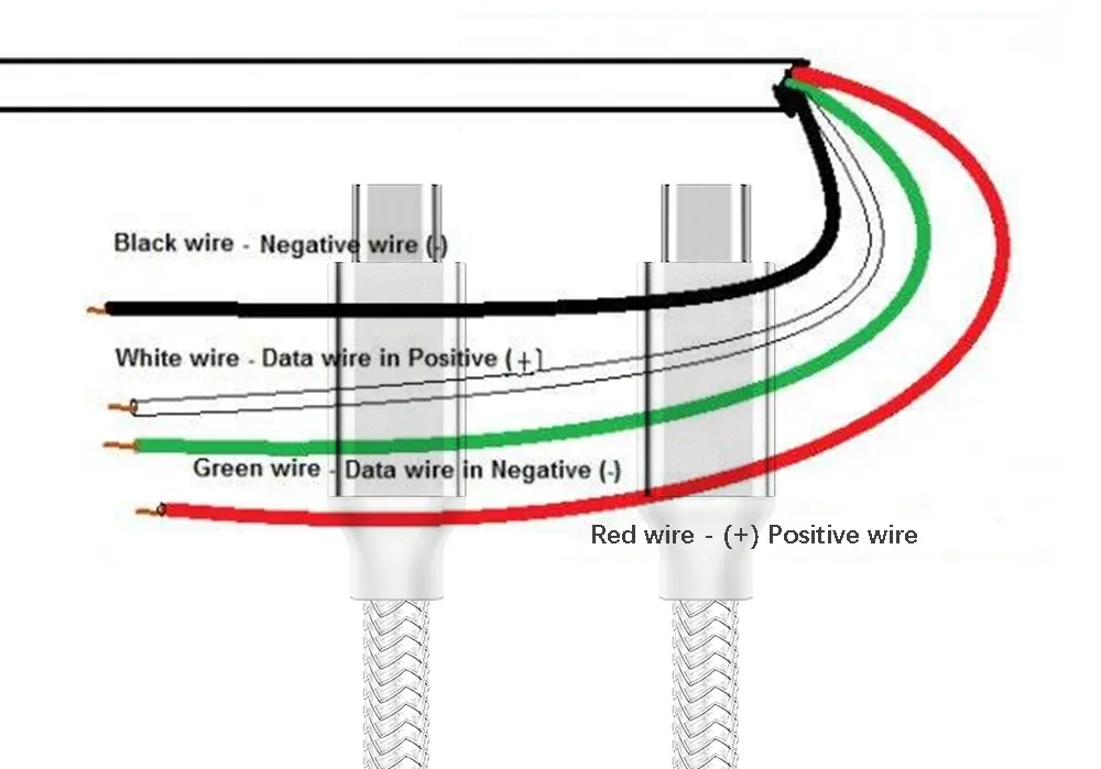
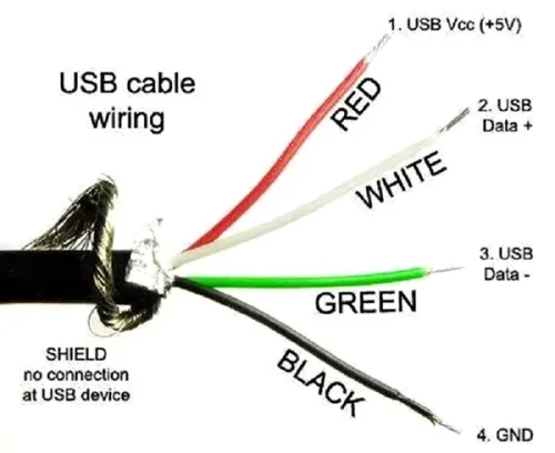
USB-C has become ubiquitous, powering everything from phones to laptops and cameras. Its small size and reversible connector make it superior to older USB standards. It supports faster data transfer and higher power delivery. But have you ever wondered what’s inside those tiny connectors? In this article, we’ll explore the inner workings of USB-C cables, focusing on the positive and negative wires. Understanding their roles will help you use USB-C technology safely and efficiently in your projects. Keep reading to learn more... Positive and negative wires are critical in USB-C cables, playing a vital role in both power and data transmission. In this section, we’ll explain what these wires do and how they work together to ensure smooth operation. The positive wire carries the voltage needed to charge devices or power peripherals. It’s usually colored red in USB-C cables. This wire connects to the VBUS pin in the connector, providing power to the connected device. It also facilitates data transmission through independent data channels (TX1+/D1+/RX2+ and TX1-/D1-/RX2-) to ensure seamless communication between devices. The negative wire completes the electrical circuit, acting as the return path for the current. It’s typically black in color and connects to the Ground (GND) pins. This wire ensures proper grounding, which stabilizes the electrical flow and enhances data transmission reliability. Without it, the system would not function properly. For any USB cable to function properly, it must have a complete positive and negative wire system. The positive wire delivers power from the source to the device, while the negative wire serves as the return path for the current. Together, they form a closed loop that enables smooth power flow. This collaboration ensures that devices receive the power they need safely and efficiently. USB-C cables also enable data transfer between devices. Here’s how the positive and negative wires contribute: In summary, the positive and negative wires in USB-C cables are essential for both power and data transmission. They ensure safe and efficient power delivery while supporting high-speed data transfer through proper grounding and signal management. USB-C cables are designed to support high-speed data transfer, power delivery, and video output in a compact and reversible connector. To understand their functionality, let’s explore their structure and how the positive and negative wires are integrated. Structure of USB-C Cables: A typical USB-C cable consists of multiple layers and components. The outermost layer is usually made of durable materials like PVC or TPE, protecting the internal components from damage. Beneath this, there are layers of shielding—braided and foil shields—to protect against electromagnetic interference (EMI) and radio frequency interference (RFI). Inside the cable, individual wires are insulated with materials like PE or PP to prevent short circuits and cross-talk. Data wires are often twisted to reduce interference and maintain signal integrity. The core of the cable contains multiple conductors, each responsible for specific signals. The positive and negative wires are crucial, as they deliver power and complete the circuit for data transmission. The positive wire connects to the VBUS pin, delivering power to the device. The negative wire connects to the GND pins, completing the circuit and ensuring proper grounding. Together, they ensure that power flows smoothly and data is transmitted accurately. Identifying the positive and negative wires in USB-C cables is essential for proper usage. While color coding is common, it can vary between manufacturers. Here’s what you need to know: USB Wire Color Coding: USB cables typically have four internal wires. Two are for power delivery (positive and negative), and the others handle data transfer. With USB 3.0, the design becomes more complex, incorporating additional wires for high-speed data transfer. When you inspect a USB cable, you’ll often see wires in different colors. These colors usually represent specific functions: Some cables may use different colors, such as orange instead of red for the positive wire. Always refer to the cable’s documentation for accurate identification. While red and black are common for power wires, variations exist, so don’t rely solely on color coding. Correct polarity in USB-C cables is critical for safe and efficient device operation. Polarity refers to the proper alignment of positive and negative wires, ensuring proper power delivery and data transmission. When the polarity is correct, devices receive power as intended, preventing damage to sensitive components. Incorrect polarity can cause short circuits, overheating, or even catastrophic failures, rendering devices inoperable. Proper polarity also ensures operational efficiency by providing a stable power supply. Devices rely on this stability to function consistently and maintain performance. Incorrect polarity can lead to malfunctions or erratic behavior, disrupting normal operations. Furthermore, USB-C cables are used for both power and data transfer. Correct polarity is essential for maintaining data integrity, ensuring accurate and reliable communication between devices. Incorrect polarity can corrupt or lose data, particularly in mission-critical applications. The consequences of improper wiring can be severe. Incorrect polarity can damage components permanently, pose fire hazards, and lead to overheating. Data corruption is another risk, resulting in lost or incomplete data transmission. Damaged devices often fall outside warranty coverage, increasing repair or replacement costs. Ensuring correct polarity avoids these issues and provides peace of mind. The quality of positive and negative wires in USB-C cables depends on several factors. These factors determine the overall performance, durability, and safety of the cables. Here’s what matters most: The quality of positive and negative wires ultimately determines the performance of the cable. Adhering to standards and conducting thorough testing ensures reliable and high-quality products for various applications and environments. We all know that USB-C cables contain multiple wires for power delivery and data transfer. Vbus (positive power), GND (ground power line), D+ and D- (USB 2.0 data transfer differential pair), RX and TX pins (high-speed data transfer differential pair) are all positive and negative in nature. These wires transmit power and data between devices. In today’s world of diverse devices, identifying the positive and negative wires of USB-C is crucial. Whether you’re building custom cables, troubleshooting, or ensuring reliable connections, understanding USB-C wiring is invaluable. Let’s explore practical methods to detect these wires and ensure safe and efficient connections. A multimeter is the best tool for identifying USB-C wires. Here’s how to use it: This method is straightforward and reliable, ensuring accurate identification of power wires. Multimeters can also help identify USB 2.0 data lines: Continuity mode helps confirm data wires without an active connection. The continuity test identifies the ground (GND) wire: This method is safe and easy to perform without powering the cable. While not foolproof, color coding can help identify wires: Color coding varies between manufacturers, so use a multimeter or oscilloscope for verification. To accurately identify high-speed data lines (RX and TX): An oscilloscope provides a visual confirmation of data transmission characteristics. Refer to the USB-C pinout diagram for a visual guide. The symmetrical design can be tricky, but the diagram clarifies which pins correspond to power and data lines. Find reliable pinouts in our USB-C Pinout Specification document. Think of your USB-C cable as a complex partner. The data lines act as the nervous system, while the power lines are the muscles. Each wire plays a specific role, ensuring seamless communication. With the right tools, you can decode this intricate system and ensure smooth connections. By mastering these methods, you’ll not only identify USB-C wires but also enhance the performance and lifespan of your devices. Happy tinkering! APPHONE’s Commitment to Quality: At APPHONE, we ensure our USB-C cables meet the highest standards through rigorous testing and meticulous manufacturing. Our high-purity copper cores guarantee excellent conductivity and durability. Every cable undergoes multiple quality checks to meet our strict standards. Learn more about our manufacturing process in our USB Cable Manufacturing Process article. Our products reflect our dedication to quality and customer satisfaction, setting a benchmark across our product line. Understanding the positive and negative wires in USB-C cables is essential for safe and effective charging and data transfer. By using tools like multimeters, continuity tests, and oscilloscopes, you can accurately identify and troubleshoot these wires. At APPHONE, we take pride in delivering high-quality USB-C cables and accessories. Our rigorous testing and innovative manufacturing processes ensure our products meet the highest standards of quality and reliability. Whether you need USB data cables, adapters, fast chargers, or other accessories, we have solutions tailored for you. A typical USB phone charger cable contains four wires: These wires handle charging and data transfer functions. USB-C cables can vary, but they often contain multiple internal wires, including power and data lines. While traditional color coding like red for positive and black for negative may not apply universally, USB-C cables are designed with specific power delivery and data transfer protocols. It’s best to refer to the cable’s documentation or use a multimeter for precise identification. Typically, there is a red wire for positive or a black wire with a red stripe. Sometimes, the clip has a "+" symbol. Occasionally, both wires are black, with the positive wire having a red sheath. Positive numbers are denoted with a "+" sign, while negative numbers are marked with a "−" sign. If there is no sign, the number is assumed to be positive. In many regions, electrical codes specify colors for live and neutral wires. In the United States, live wires are typically black, red, or another color, while neutral wires are often white or gray. A typical USB phone charger cable contains four wires: These wires handle charging and data transfer functions."}},
{"@type": "Question", "name": "Does a Type-C charger have red and black wires?", "acceptedAnswer": {"@type": "Answer", "text": " USB-C cables can vary, but they often contain multiple internal wires, including power and data lines. While traditional color coding like red for positive and black for negative may not apply universally, USB-C cables are designed with specific power delivery and data transfer protocols. It’s best to refer to the cable’s documentation or use a multimeter for precise identification."}},
{"@type": "Question", "name": "What is positive and negative about a 12v cable?", "acceptedAnswer": {"@type": "Answer", "text": " Typically, there is a red wire for positive or a black wire with a red stripe. Sometimes, the clip has a "+" symbol. Occasionally, both wires are black, with the positive wire having a red sheath."}},
{"@type": "Question", "name": "What is the negative and positive wire symbol?", "acceptedAnswer": {"@type": "Answer", "text": " Positive numbers are denoted with a "+" sign, while negative numbers are marked with a "−" sign. If there is no sign, the number is assumed to be positive."}},
{"@type": "Question", "name": "How to identify live and neutral wires?", "acceptedAnswer": {"@type": "Answer", "text": " In many regions, electrical codes specify colors for live and neutral wires. In the United States, live wires are typically black, red, or another color, while neutral wires are often white or gray."}}
]}
Body Parts Chongqing Zhongheng Chuangxin Auto Parts Co., Ltd , https://www.zhcx-autoparts.com
What Are USB-C Positive and Negative Wires?
How Do Positive and Negative Wires Enable Power Transmission?

How Do Positive and Negative Wires Facilitate Data Transmission?
Understanding USB-C Cable Construction
Which Wires Are Positive and Negative in USB-C?
Why Is Proper Polarity Important in USB-C Cables?
Factors Influencing the Quality of USB Positive and Negative Wires
Methods to Detect Positive and Negative Wires in USB-C
Multimeter Magic:
Continuity Test:
Wire Color Coding:
Oscilloscope:
USB-C Pinout Diagram:
What Are the 4 Wires in a Phone Charger?
Does a Type-C Charger Have Red and Black Wires?
What Is Positive and Negative About a 12v Cable?
What Is the Negative and Positive Wire Symbol?
How to Identify Live and Neutral Wires?
Share This Article: